STARLIGHT: A model rocket development board!
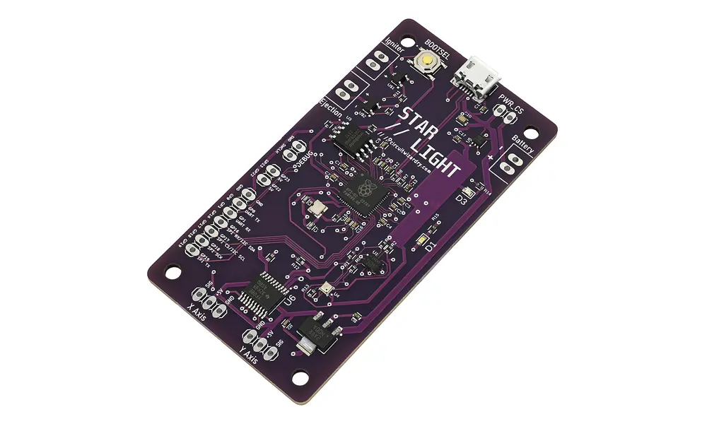
The Starlight Rocket Control Unit is ideal for model rocketry. Designed for use in 75mm diameter rocket tubes although you can get it in smaller ones too, it ensures accuracy and stability for your next launch. Its high-quality design will take your model rocketry to the next level.
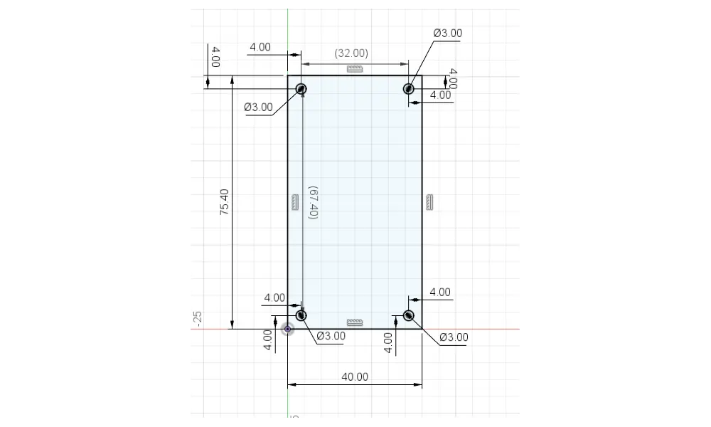
What's more this board is only 75.4mm long and 40mm wide.
This version does not have headers and terminals pre-soldered on. We also stock a version with headers if required.
For beginners & pros alike!
With sensors such as pressure, temperature, gyroscope, and accelerometer all packaged onto the board, this board allows you to monitor every part of your model rocket during liftoff and recovery!
Furthermore, the board has I/O ports for two micro-servos, allowing you to fix a thrust vector control system to your rocket without any messy wiring! Simply plug your two servos in and you're good to go.
Simple and adaptable!
Want to connect more sensors or peripherals to your STARLIGHT board? No sweat! This board also comes equipped with eight GPIO outputs, including a SPI bus, an I2C bus, and a UART bus! Two of the eight GPIO are 5 volt GPIO, so you can also interface this 3.3V device with 5V logic!
There is plenty of online documentation for launching your rocket with STARLIGHT will be a breeze! If you're looking to turn your rocket into an electronic masterpiece, look no further than Starlight.
Features:
- RP2040 for blazing-fast code execution and easy programming. You can write your firmware in Python!
- ICM-42605 6-axis IMU: Gyroscope and accelerometer
- Level shifter to allow use of 5V servos with the 3.3V RP2040
- Dual temperature sensing for added redundancy and protection from overheating
- BMP388 pressure sensor for altitude determination and flight tracking
- 6x 3.3V GPIO pins, plus exposed SPI, I2C, and UART interfaces for even more versatility
- 2x 5V GPIO pins, made possibly by the on-board level shifter
- 16MB of flash storage, for storing flight data and firmware
- Indicator LEDs for power and runtime
- Micro-USB for easy programming
- Input voltage 5-18V
- Dual voltage regulators for both 3.3V and 5V directly on the board
- Two servo outputs to allow for optional thrust loop vector control interface
- M3 mounting holes, mounting hardware NOT included
- Digital guide included
Specifications:
- Input voltage: 5-18V
- Interface type: Micro-USB, cable not included
- On-board sensors: Gyroscope, Accelerometer, Dual Temperature Sensors, Pressure (ICM-42605, BMP388)
- Microcontroller: Raspberry Pi RP2040
- Board voltage: 3.3V for GPIO, 5V for servos and 5V GPIO
- GPIO Voltage: There are 8 total GPIO (NOT including servos). 6 of the GPIO are 3.3V, and 2 are 5V.
- Servo GPIO: There are 2 ports to plug 3-pin servos into. These ports are 5V.
- Dimensions: 40mm * 75.4mm
Pinout
STARLIGHT has many pins for use in your rocketry projects.
- Igniter: This is a high-power rail intended for use with ignition systems to automatically light your engine. It is connected to an AO3400 MOSFET (max. pulse current 30A) controlled by pin GP6 on the RP2040. The AO3400 MOSFET is connected directly to the power supply, so depending on the battery voltage you use this terminal’s voltage will vary.
- Ejection: This terminal is wired just like the Igniter rail is, with another AO3400 MOSFET connected to pin GP7 on the RP2040.
- Battery: This is where you should plug in your battery. Note the polarity on the board! Plugging in the battery backwards could lead to frying your STARLIGHT board. STARLIGHT accepts a wide range of input voltages, from 5-18V.
- PWR_CS: This is a jumper that allows you to connect and disconnect the battery easily from STARLIGHT. In order to protect the board and your computer, never have the battery connected to the board while the board is plugged into USB!! PWR_CS allows you to disconnect the battery from the board without having to unscrew the leads from your terminals. Simply remove the jumper on these two pins to disconnect the battery. Put the jumper back, and the battery will be reconnected. There is no on-board charging circuit.
- GP0: This is directly connected to the RP2040’s GP0 pin. This also doubles as a UART TX pin.
- GP1: This is directly connected to the RP2040’s GP1 pin. This is the UART RX pin.
- GP16: This is directly connected to GP16 on the RP2040. It is also SPI RX/I2C SDA (per the RP2040 pinout).
- GP17: Directly wired to GP17, SPI CS/I2C SCL
- GP18: Directly wired to GP18, SPI SCK
- GP19: Directly wired to GP19, SPI TX
- GP22 (5V): This is a pin connected through the level shifter to the RP2040’s GP22 pin. This is a 5 VOLT LOGIC PIN!!!
- GP23 (5V): This is a pin connected through the level shifter to the RP2040’s GP23 pin. This is a 5 VOLT LOGIC PIN!!!
- X AXIS: This is a 3-pin connector for use with servos. The SIGNAL pin is connected to GP11 on the RP2040. This is a 5 VOLT CONNECTOR!!!
- Y AXIS: This is a 3-pin connector for use with servos. The SIGNAL pin is connected to GP12 on the RP2040. This is a 5 VOLT CONNECTOR!!!
- Note: There are also two debug pins exposed, just in case they are required. In most cases, you can ignore these pins.
On-board connections
Some of the RP2040 pins are connected to other chips on the board.
- On-board I2C: This board uses the I2C bus to communicate with the on-board sensors. For the on-board I2C, SDA is connected to GP2 and SCL is connected to GP3.
- On-board LED: The on-board LED is connected to GP24.
- Level shifter enable (IMPORTANT!!!): GP14 on the RP2040 is connected to the ENABLE pin on the on-board level shifter. Set GP14 to HIGH to enable the level shifter, subsequently enabling the servos and the 5V GPIO.
Getting Started
Now, you may be asking – How do I actually write code for this board? There are loads of tutorials for other boards on the market, but STARLIGHT is somewhat unique in a sense. The act of programming it will be the same, but the features that come pre-packaged with the board trump many other current boards on the market.
- Download the STARLIGHT UF2 for this board. This board uses a custom UF2 file, you can download it from our listing here under the attachments tab below.
- Install Thonny IDE. This is how you’re going to write and upload code to the board. You can find a link to download it here.
- Plug in your board: Drag the .uf2 file into the USB mass storage device that the board boots into by default, give it some time to copy over. If this operation succeeds, the board will reboot and you will no longer see it as a mass storage device.
- Select the MicroPython interpreter. This can be done in the bottom right of Thonny IDE.
Reading Sensors & Controlling Servos
Now that you’ve been able to write your first bits of code for the STARLIGHT control board, you’re probably wondering – Where do I go from here? Printing “Hello World” is a far cry from launching a model rocket with this board. Luckily, we have everything you need to succeed with STARLIGHT neatly packaged in a GitHub repository.
No reviews found
All items on our website shown as in stock, are in our warehouse ready to ship unless stated otherwise on the product page.
We aim to ship orders within 1 working day of ordering on your chosen shipping method.
We do not guarantee this however, especially at extremely busy times of the year. Therefore if you do require your order urgently, please drop us a email after you order to let us know.
Please note that you must use a courier option if your order contains rocket motors, you can not use the Royal Mail for orders with motors. The website should automatically disable the Royal Mail shipping option once these items are added to your cart. However in the case of a website mistake you will need to use the courier option.
Orders will ship on your chosen courier, all UK Mainland couriers we offer are a next day service. The couriers however do not offer us a guarantee on this, so we are unable to pass one along.
Over 95% of our orders do arrive next day as intended.
If you require Saturday delivery there is a Saturday delivery option on the checkout page. DHL do not offer Saturday delivery by default.
You can use the Royal Mail option for smaller items up to 2Kg in weight as long as they do not contain motors.
Please be aware if you require AM or Saturday delivery these orders may still take up to 1 working day to dispatch. We do, however, prioritise express orders for dispatch.
If an item was sent un-tracked the delivery date is agreed to be 2 (two) days after shipment.
Returned items should be undamaged and in a good condition suitable to be sold again. They need to arrive with us in this condition.
You must package the item well so that damage does not occur in transit, although you do not need to use the original packaging.
We will offer to replace the faulty or damaged item, or refund you in full at your preference.
In regards to missing parts of kits we reserve the right to replace the required parts rather than the entire kit.
If the item arrives damaged or faulty we will of course still offer a refund or replacement on custom orders.
If your item has been dispatched then we will need to investigate with our couriers before continuing with our refund process. This may take up to 14 working days to complete although is usually a far quicker process. We will always offer a full refund or replacement for lost items.
If you paid by BACS we will require your bank details to send a repayment via BACS.
BACS payments should usually arrive in your account the same day, however please allow up to 5 working days.
If you paid by PayPal (Debit or Credit Card) the refund will usually be processed on to the payment method used to make the payment. This may take up to 7 working days to complete but is usually within 3-5 working days.
If you paid via credit or debit card the refund will usually be with you within 1-5 working days.
If you paid by cheque we are unable to process a refund by any method other than cheque and this will be posted 2 working days after your payment cleared at the earliest. (This is the final clearing date defined by the latest time period in which the cheque can be reversed, not the initial funds release date.)
 Altimeter Cloud Beta
 Real stock in house
 90-day returns
 Next day delivery